English
  日本語
日本語  한국어
한국어  français
  Deutsch
  Español
  italiano
  русский
  العربية
  Türkçe
  tiếng việt
Jul 20, 2026
The main difference between a horizontal steering wheel and a vertical steering wheel is the arrangement of the traction motor and drivetrain. This changes how the assembly fits into the chassis, how much space it needs while steering, and how its components can be serviced.
For an AGV manufacturer, the useful comparison is between complete assemblies under the same vehicle requirements. Load capacity, torque, efficiency and service life must be checked against the selected configuration and operating conditions.
Horizontal and vertical describe the drive module’s mechanical layout, particularly the traction-motor orientation; both layouts can combine propulsion with controlled steering.
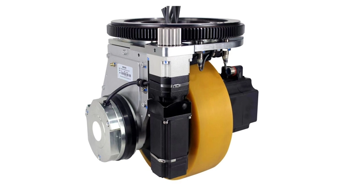
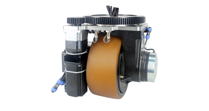
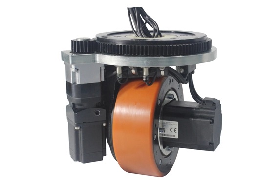
A horizontal assembly positions the traction motor horizontally within the drive unit. This can support a low overall profile, depending on the motor, gearbox and mounting design. The motor and accessories also need lateral clearance.
When comparing horizontal steering wheels, inspect the entire assembly through its steering range. A low module can still conflict with a battery compartment, chassis rail or cable route.
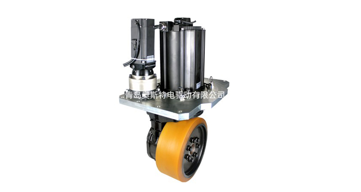
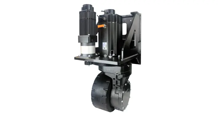
A vertical assembly positions the traction motor upright, with the drivetrain arranged around that layout. The motor may occupy space above the mounting interface, while the wheel and transmission occupy space below it.
For vertical drive wheels, check the space on both sides of the mounting plane. A forklift-type chassis with a dedicated drive compartment may accommodate this arrangement differently from a platform with a continuous low deck.
The layout name does not specify the gear type, steering angle or whether suspension is included. For the distinction between drive modules and steered support wheels, see our guide to AGV steering wheel types and functions.
A drawing-based comparison uses identified dimensions and reference points to evaluate packaging. The three Honest Edrive drawings below show why overall height, mounting footprint and steering clearance must be read separately.
| Illustrated assembly | Vertical dimension shown | Radius label | Installation implication |
|---|---|---|---|
| HW210 horizontal drive wheel Published drawing | 277 mm | R175 mm | The illustrated unit has a low vertical profile. Include the side-mounted motor and steering hardware in the clearance review. |
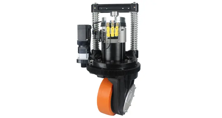
| HL230 vertical drive wheel with suspension Published drawing | 665 mm | R271 mm | The drawing includes an upright motor and suspension structure. Confirm mounting points and the envelope throughout the suspension travel. |
| HL343 vertical steering wheel Published drawing | 820 mm | 198 mm, labelled turning radius | The drawing also shows a 510 × 400 mm mounting-plate outline. The radius alone does not describe the full installation footprint. |
Source: Honest Edrive’s linked product drawings, checked September 17, 2026. Values describe the illustrated assemblies, not every configuration in each family. Confirm units, drawing revision, model suffix, reference surfaces and suspension position on the agreed installation drawing.
A total vertical dimension describes the illustrated assembly’s extent. It does not, by itself, specify the finished vehicle deck height. Identify the floor-to-mounting-plane distance, the projection above that plane and any movement caused by suspension before comparing it with the chassis.
The 277, 665 and 820 mm figures therefore provide packaging references. They do not establish equivalent load ratings or prove that one layout is universally more compact.
The HL343 drawing provides a useful example: its 198 mm radius label appears alongside a mounting plate measuring 510 × 400 mm. Both dimensions matter. Check the indicated rotating parts, stationary structure, connectors and vehicle clearances in the assembly model.
A module’s rotation radius also differs from the vehicle’s turning radius, which depends on wheel locations, commanded angles, chassis dimensions and the payload envelope.
The installation envelope is the space needed for the assembled module and its permitted movement. Maintenance access adds the space needed to reach and remove components.
| Review item | Horizontal-layout focus | Vertical-layout focus |
|---|---|---|
| Height and mounting plane | Check the complete low-profile assembly, mounting plate and clearance to the deck. | Separate the motor projection above the mounting plane from the wheel and gearbox below it. |
| Steering sweep | Include lateral motor and brake projections throughout the allowed angle range. | Check the rotating assembly and stationary mounting structure at their respective heights. |
| Suspension | If fitted, check the complete moving envelope and contact-load range. | For a suspended assembly such as the illustrated HL230, include brackets, springs and moving parts. |
| Wheel replacement | Confirm access to retaining hardware and the actual wheel-removal direction. | Check whether the wheel can be removed below or beside the chassis without dismantling adjacent equipment. |
| Motor, brake and feedback service | Reserve access around side-mounted components and their connectors. | Reserve access above and around upright components, according to the service procedure. |
| Cables and connectors | Check routing near lateral projections and steering motion. | Check routing around the mounting plane, motor and any suspension movement. |
For either layout, model cable movement as part of the clearance check. igus’s rotary cable-guidance systems illustrate that rotation angle, bend radius and strain relief are separate design considerations. Use the requirements of the selected cables and routing arrangement.
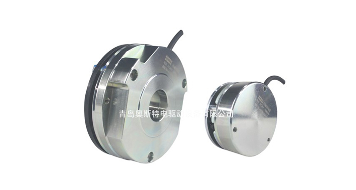
Ask the supplier to identify the removal path for the tyre, brake, encoder and motor. A component being visible does not mean it can be replaced with the surrounding chassis assembled. Compare the actual service procedure rather than assuming that horizontal or vertical units are always easier to maintain.
Load support, propulsion and thermal duty are separate requirements that must be verified for each drive-wheel configuration.
Establish the load at each wheel across the relevant payload positions and operating conditions. Clarify whether a quoted capacity applies to a tyre, complete module or vehicle, and whether it is static or dynamic. Blickle’s load-capacity guidance explains why wheel ratings depend on test and application conditions. Obtain the corresponding conditions for the proposed AGV module.
For propulsion, compare wheel-output torque and speed, motor-drive limits and the required travel cycle. maxon’s gearhead technical guide distinguishes gear ratio, efficiency, continuous torque and short-term loading. Motor orientation alone cannot establish these properties.
Continuous operation also depends on motor and gearbox losses, ambient temperature and heat transfer within the installed chassis. Compare temperature rise and energy consumption under a defined route, payload and duty cycle. A general claim that one orientation is more efficient is insufficient for purchasing.
Likewise, a vehicle payload above 1 tonne does not create an automatic requirement for a vertical drive wheel. The relevant evidence is the selected assembly’s capability under the calculated wheel loads and operating duty.
The suitable layout is the configuration that meets the vehicle’s performance requirements while fitting its mounting, movement and service envelopes.
Begin with assemblies that fit the available vertical space, using the HW210 drawing as one horizontal-layout reference. Next, check side clearance around batteries and frame members through the full steering sweep. Confirm the load and drive ratings separately.
Review vertical assemblies such as the illustrated HL230 or HL343 against the available compartment. Identify the mounting plane, motor projection and service opening. If suspension is required, specify its operating position, travel and preload rather than relying on a product-family name.
Compare complete vehicle manoeuvres. Wheelbase, steering-angle limits, chassis corners and payload overhang all affect clearance. Check steering repeatability and docking performance on the integrated vehicle; a shorter module does not guarantee a smaller aisle requirement.
Use the product layout to build a shortlist, then compare configuration-specific drawings and operating limits. Before approval, overlay the assembly in the chassis CAD, check steering and suspension movement, and confirm that normal service tasks remain accessible.
Our AGV wheel selection guide provides the wider load, floor and RFQ checklist.
Send your AGV chassis requirements to Honest Edrive with the available space above and below the mounting plane, steering range, wheel-load estimates and required service access. Request the current installation drawing for the proposed configuration.
Horizontal and vertical layout terms describe packaging; model-specific drawings and operating data determine suitability.
It is a steerable wheel assembly with a horizontally arranged traction motor. The layout can support a low profile, but the complete installation height and steering envelope must be checked on its drawing.
It is a drive assembly with an upright traction-motor arrangement. In a steering version, the module also controls wheel orientation. Motor placement alone does not define its load capacity or efficiency.
No. Compare the complete assembly’s load rating, mounting structure, traction capability and duty limits. A vehicle’s total payload cannot determine the required layout without its wheel-load distribution and operating requirements.
No. A module radius describes a local geometric feature or rotation envelope. Vehicle turning clearance also depends on wheel positions, steering commands, chassis dimensions and payload overhang.
No. Identify the mounting reference and the portions above and below it. Include chassis structure, clearances and suspension movement before establishing the finished deck height.
There is no universal ranking. Compare duty, loading, environment, wear components and the prescribed service procedure. Ask for relevant endurance evidence and service intervals for the proposed configuration.