English
  日本語
日本語  한국어
한국어  français
  Deutsch
  Español
  italiano
  русский
  العربية
  Türkçe
  tiếng việt
Jul 30, 2026
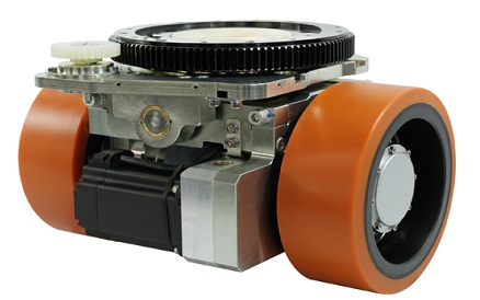
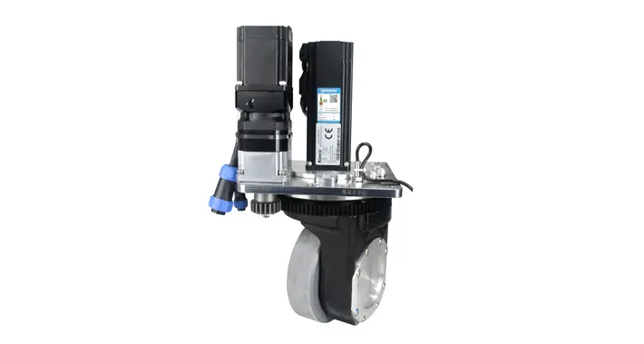
An AGV steering wheel is a wheel assembly whose direction can be controlled to guide an automated guided vehicle. Some assemblies combine propulsion and steering; others steer a supporting wheel while separate drive units move the vehicle.
For a vehicle manufacturer, identifying that role is the first step toward choosing the right architecture. A steering motor, a traction motor and a passive swivel mechanism perform different jobs, even when product names use similar terms.
An AGV steering wheel provides controlled wheel orientation; an AGV steering drive wheel also supplies powered rotation for propulsion.
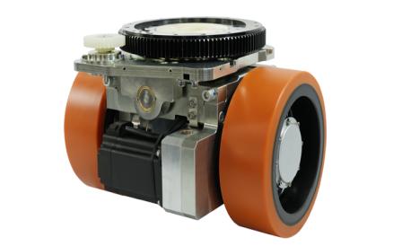
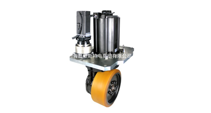
In an integrated steering drive module, the traction motor rotates the wheel around its axle, while the steering mechanism turns the assembly around its steering axis. The vehicle controller coordinates wheel speed and direction with the other wheels on the chassis.
An actively steered support wheel has controlled orientation but relies on other drive units for propulsion. A conventional passive caster swivels in response to vehicle movement and floor forces. These distinctions determine which motors, feedback signals and control functions a quotation should include.
AGV wheel types are best distinguished by their propulsion, steering and support functions. Vehicle steering arrangements should then be considered separately.
| Type or arrangement | Propulsion | Directional control | Key distinction |
|---|---|---|---|
| Steering drive module | Powered wheel rotation | Controlled orientation of the wheel assembly | Combines traction and steering at one wheel position. |
| Actively steered support wheel | No traction drive in this role | An actuator controls wheel orientation | Supports load and follows coordinated steering commands. |
| Passive swivel caster | Unpowered | Swivels mechanically as the vehicle moves | No commanded steering angle; can still support an automated vehicle. |
| Differential drive: vehicle arrangement | Separately powered left and right wheels | Vehicle turns through different wheel speeds | A conventional fixed-axis differential base does not need steering pivots at its drive wheels. |
Blickle’s swivel castor guide describes the wheel and swivel bracket that allow a caster to pivot around a vertical axis. A freely swivelling caster should therefore be distinguished from a wheel whose steering angle is actively controlled.
For differential drive, ROS 2’s differential-drive controller documentation explains how vehicle velocity commands become wheel commands, with wheel separation and radius affecting motion. Load capability and positioning performance depend on the implementation; differential drive is not inherently restricted to light-duty vehicles.
Horizontal and vertical describe the drive assembly’s mechanical layout. Both can incorporate traction and steering. Compare horizontal steering wheels by their installation envelope, and vertical drive wheels by their height, mounting arrangement and drivetrain configuration.
These layout names do not describe the direction of the steering axis or guarantee a particular turning radius. The vehicle’s wheel positions and coordinated motion determine how the complete chassis manoeuvres.
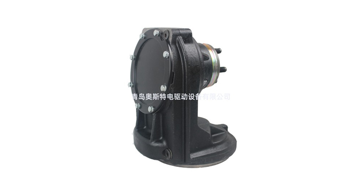
A steering drive module combines mechanical load support, powered wheel rotation, steering actuation and feedback. The components supplied depend on the selected configuration.
| Component | Function | What to confirm |
|---|---|---|
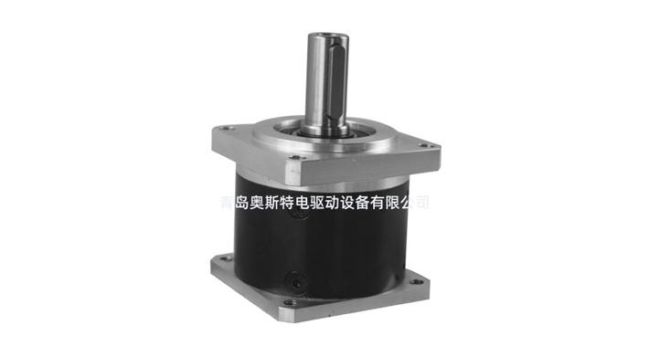
| Traction motor and reduction gearing | Rotate the wheel to produce tractive force at the floor. | Wheel-output torque, operating speed, continuous duty and drive compatibility. |
| Steering motor and transmission | Turn the wheel assembly to the requested orientation. | Steering torque, response, backlash, angle limits and allowable turning conditions. |
| Steering bearing and mounting structure | Support the rotating assembly and transfer loads to the chassis. | Load directions, mounting fasteners, stiffness and full steering clearance. |
| Encoders and reference sensors | Provide rotation or angular-position feedback. | Sensor location, resolution, interface, reference procedure and calibration. |
| Wheel, tyre and hub | Carry contact load and transmit force to the floor. | Tread specification, grip, wear, floor compatibility and replacement method. |
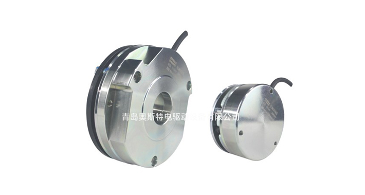
| Brake, where fitted | Provide the holding or stopping function specified for the assembly. | Rated function, supply voltage and control sequence. |
The vehicle controller requests wheel speed and steering angle. Motor drives regulate the corresponding motors, using feedback to track those commands. During a turn, the controller coordinates each wheel’s direction and speed with the chassis geometry so the wheels follow compatible paths.
Navigation remains a vehicle-level function. Texas Instruments’ mobile robot architecture separates sensing, computing and motor control. A steering wheel executes motion commands; it does not independently plan routes or locate the vehicle within a warehouse.
Steering feedback and vehicle positioning are different measurements. An encoder can report rotation or angle, but vehicle positioning also depends on calibration, mechanical play, tyre deformation, slip and navigation sensors. A motor or encoder specification alone cannot establish millimetre-level docking accuracy.
For more detail on propulsion and control, see the working principle of AGV drive wheels.
AGV steering assemblies are applied according to the role of each wheel and the vehicle’s required motion. Product specifications help distinguish those roles before detailed selection.
| Published example | Relevant specification | What it illustrates |
|---|---|---|
| HW210-SM750-48-B | 0.75 kW traction motor and 0.2 kW steering motor, both listed at 48 V; steering limit ±110°. | Separate traction and steering functions within a horizontal assembly. The stated angle is a limited steering range, not continuous rotation. |
| HL230-AC1600-24-22-FD-SM | 1.6 kW AC induction traction motor and 0.4 kW steering motor; vertical layout with suspension. | A configuration presented for forklift-type AGVs. Suspension travel, preload and electrical requirements still need configuration-specific confirmation. |
| HK250 controllable universal wheel listing | The specification table lists a 0.4 kW, 48 V steering motor; travel-motor and rated-traction fields are unpopulated. | Evidence of controlled steering, without a specified traction drive in that table. Review it as a candidate for a steered support position and confirm the supplied configuration. |
Sources: the linked manufacturer pages, checked September 17, 2026. These examples explain component roles; they are not vehicle-level performance approvals. Use the current drawing and agreed configuration for purchasing.
In pallet transport and factory logistics, the chassis may combine steering drive modules with support wheels. Where support-wheel orientation must be controlled, review AGV swivel wheels with controlled steering and confirm the propulsion role of every proposed unit.
For forklift-type AGVs, examine the relationship between the steering assembly, load wheels and changing payload position. For multi-module transport platforms, check whether all wheel paths can be coordinated during turning or lateral travel. A module’s steering range alone does not demonstrate that the vehicle can move sideways.
Electronics, pharmaceutical and other controlled environments add application requirements such as conductivity, particle generation or cleaning compatibility. These properties require evidence for the selected assembly and should not be inferred from an “AGV” designation.
Choosing an AGV steering wheel starts by assigning propulsion, steering and support functions to each position on the chassis.
Define the required movements. Specify straight travel, reversing, docking, turning and any lateral movement. Check the complete vehicle envelope, including the payload and wheel sweep.
Verify the assembly interfaces. Confirm mounting geometry, traction and steering ratings, feedback signals, motor drives, communication functions and brake requirements. A shared voltage or bus name does not establish complete compatibility.
Check the limiting conditions. Review wheel reactions across payload positions, steering at standstill versus while rolling, floor contact and cable movement. State whether a quoted steering angle is a software limit, mechanical limit or usable operating range.
Validate the result on the vehicle. Record steering tracking, current, temperature, tyre scrub and docking repeatability under representative loads. If steering errors occur, distinguish feedback or reference errors from mechanical play, slip and incompatible wheel commands before changing controller settings.
For the complete load, floor and quotation checklist, use our AGV wheel selection guide.
A useful AGV steering-wheel specification states whether the assembly drives, steers, supports or combines these functions. That definition makes model comparisons clearer and gives the vehicle team a practical basis for checking mechanical fit and control integration.
Discuss your platform with Honest Edrive: request an AGV steering wheel configuration review with your wheel layout, vehicle and payload masses, required movements, available installation space and control interface.
AGV steering-wheel specifications describe a module’s functions and limits; its final suitability depends on the complete vehicle.
No. A steering drive module includes propulsion, while an actively steered support wheel controls orientation without providing traction. Check the travel-motor, steering-motor and traction fields in the exact configuration’s datasheet.
The names are used inconsistently. A swivel wheel may be a passive caster or an actively steered support unit. Confirm whether it includes a traction motor and whether its steering angle is commanded or free to swivel.
Yes. A conventional differential-drive vehicle turns by running its left and right drive wheels at different speeds. Its drive wheels can have fixed orientations relative to the chassis, with other wheels providing support.
No. Steering travel depends on the mechanism, limits and cable arrangement. A ±110° specification describes a bounded range; it does not indicate unlimited rotation. Confirm the permitted range for the supplied assembly.
No. It provides position information for the measured rotation. Docking accuracy also depends on the encoder’s installation and calibration, mechanical behaviour, wheel slip, navigation system and vehicle control.
Potentially, if the load, motion, mechanical and control requirements match. AGV and AMR labels do not determine one mandatory wheel architecture. Compatibility must be assessed for the specific vehicle design.