English
  日本語
日本語  한국어
한국어  français
  Deutsch
  Español
  italiano
  русский
  العربية
  Türkçe
  tiếng việt
Aug 25, 2026
Heavy-duty AGV wheels must be selected as part of a complete motion system rather than by nominal load capacity alone. For high-load applications, engineers need to evaluate dynamic wheel load, traction demand, drive torque, braking performance, floor conditions, duty cycle, steering resistance and control accuracy at the same time.
A wheel with sufficient static capacity can still fail prematurely if it operates under concentrated axle loading, frequent acceleration, tight turning, long slopes or continuous multi-shift duty. The most reliable solution therefore combines a reinforced wheel structure, properly matched motor and gearbox, suitable tread material, accurate steering feedback and adequate thermal capacity.
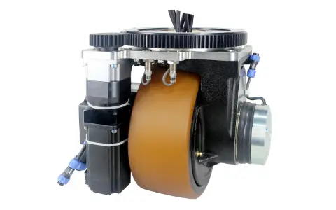
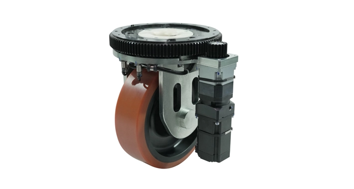
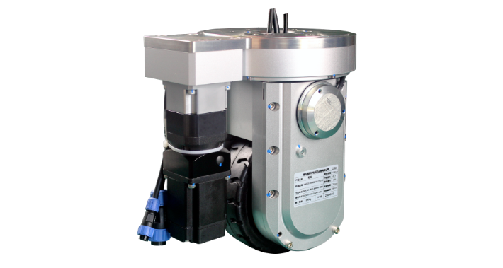
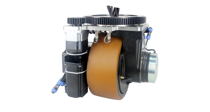
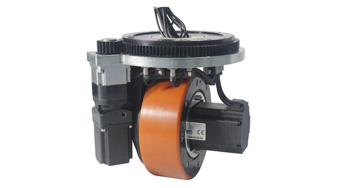
HAGV Wheel provides heavy-duty drive units covering applications from approximately 500 kg to 25 tons, including solutions for automated warehouses, ports and automotive production lines.
A heavy-duty AGV wheel must withstand more than the vertical weight of the vehicle. It is exposed to several forces simultaneously:
Radial load from the vehicle and payload
Tangential force during acceleration and braking
Lateral force during steering
Impact load at floor joints, ramps and uneven surfaces
Heat generated by the motor, gearbox, bearings and tire deformation
Torsional stress during frequent direction changes
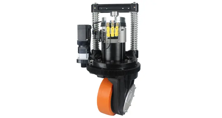
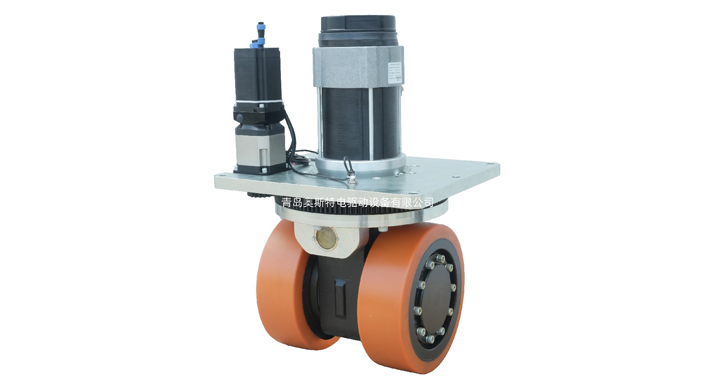
For this reason, high-load wheel modules usually require reinforced steel structures, high-capacity bearings, hardened gear components and a tread bonded securely to the wheel core. HAGV Wheel’s heavy-duty range uses reinforced hubs and hardened gear structures for industrial AGVs, forklifts, port equipment and other demanding transport systems.
The gearbox is particularly important. Increasing motor power without verifying reducer capacity, gear-tooth strength and output-bearing load does not create a reliable heavy-duty solution. The complete transmission must tolerate repeated starting torque and emergency braking torque without excessive backlash or thermal buildup.
The required wheel rating should be calculated from the maximum gross vehicle mass, not only the rated payload.
A practical preliminary relationship is:
Required wheel capacity ≥ maximum gross vehicle mass × actual load distribution × dynamic allowance
The maximum gross vehicle mass should include:
AGV chassis
Battery system
Lifting or transfer mechanism
Maximum payload
Onboard control equipment
Attachments and safety devices
The load should then be distributed according to the real center of gravity. It is rarely correct to divide the total mass equally by the number of wheels. During acceleration, braking, lifting or travel on an incline, the center of gravity shifts and one axle may carry substantially more load than another.
Engineers should also consider what happens when the vehicle crosses a floor joint or when one supporting wheel temporarily loses firm contact with the floor. In such cases, the remaining wheels may experience a much higher instantaneous load. Suspension or load-equalization mechanisms can help maintain wheel contact and reduce concentrated stress.
Final wheel capacity should be confirmed through structural analysis and full-load vehicle testing rather than relying only on a theoretical calculation.
The correct configuration depends on vehicle size, turning requirements and route complexity.
A conventional differential-drive platform uses independently controlled left and right drive wheels. The vehicle travels straight when both wheels rotate at the same speed and changes direction when their speeds differ. This layout is compact and can achieve a very small turning radius.
However, tire scrubbing can become significant when a high-load vehicle turns in place. The problem becomes more serious with wide tires, high floor friction and large distances between the drive wheels. Additional steering resistance increases motor current, tire wear, floor wear and positioning error.
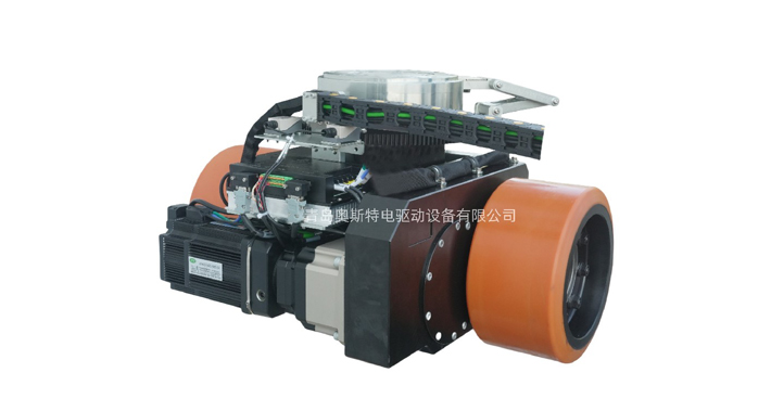
For a compact differential wheel robot, independent wheel-speed control may be sufficient. For heavier industrial vehicles, a differential steering module can provide better load distribution and smoother turning. Such a module can combine:
Two load-bearing wheels
A mechanical differential
A travel motor
A separate steering servo
An absolute steering encoder
A high-ratio steering reducer
The HAGV HW300, for example, uses a dual-wheel structure, an internal mechanical differential and absolute encoder steering. Its mechanical differential allows the two wheels to rotate at different speeds during a turn, reducing sliding between the tires and floor. The model is rated for a carrying capacity of 4,000 kg and supports CANopen, Modbus, EtherCAT and pulse-based control options.
This type of configuration is particularly useful when a high-load vehicle must combine precise steering with reduced tire scrub.
Motor power alone does not determine whether an AGV can move its load. The required wheel torque is influenced by:
Gross vehicle mass
Wheel radius
Rolling resistance
Acceleration target
Maximum gradient
Floor condition
Number of driven wheels
Transmission efficiency
Turning resistance
Required braking distance
Larger wheels improve obstacle-crossing ability but require more torque at the axle for the same tractive force. A higher reduction ratio can increase output torque, although it may reduce maximum vehicle speed. The drive therefore needs to be balanced around actual operating requirements rather than optimized for one parameter.
Traction is another limiting factor. Even a high-torque motor cannot move the vehicle effectively if the wheel slips. The available traction depends on the load acting on the driven wheel and the friction between the tread and floor.
For a high-load AGV, engineers should verify at least four operating cases:
Starting at maximum payload
Accelerating on the maximum specified incline
Turning at maximum expected axle load
Performing a controlled emergency stop
Motor current, gearbox temperature, wheel slip and stopping distance should be monitored during these tests.
Heavy-duty AGV wheel systems are most valuable where manual or conventional forklift transport creates safety, consistency or labor challenges.
AGVs transport vehicle bodies, chassis fixtures, battery packs, molds and heavy assembly components. Smooth acceleration and accurate positioning are essential because sudden motion can affect both the payload and upstream equipment.
Port AGVs operate with extremely high payloads, long travel distances and demanding outdoor conditions. Wheel systems require strong traction, high structural capacity, effective sealing and reliable thermal performance.
Heavy-duty mobile platforms may transport coils, castings, dies, machine components or fabricated structures. The wheel system must tolerate high concentrated loads and frequent contamination from dust, oil or metal particles.
Aircraft sections, engines and precision fixtures require controlled low-speed movement. Positioning repeatability and smooth steering can be more important than maximum travel speed.
High-load AGVs move pallet groups, production materials and multi-ton transfer racks. Compact steering geometry becomes important where vehicles must operate near machinery or in restricted aisles.
HAGV Wheel’s heavy-duty product range is designed for AGVs, forklifts, pallet stackers, port vehicles and other industrial mobile equipment operating from approximately one to 25 tons.
Premature wheel damage often results from system-level conditions rather than insufficient material strength.
Recommended maintenance practices include:
Inspecting tread wear and surface cracking
Checking wheel-core bonding
Monitoring gearbox noise and backlash
Confirming bearing condition
Checking mounting-bolt torque
Inspecting electrical connectors and encoder cables
Recording motor current under repeatable operating conditions
Monitoring gearbox and motor temperature
Keeping the travel route free of sharp debris
Repairing damaged floor joints
Motor-current trends are particularly useful. Increasing current on the same route may indicate rising rolling resistance, bearing damage, wheel misalignment, gearbox wear or caster interference.
Caster behavior should not be ignored. Research on differential-drive robots shows that caster alignment can generate additional resistance and motor torque demand. Under high loads, poorly positioned or undersized casters can affect path accuracy and increase stress on the drive wheels.
No. Larger wheels cross joints and obstacles more easily, but they increase axle torque requirements and installation space. Diameter, width, material and gearbox ratio must be selected together.
Common causes include insufficient driven-wheel loading, unsuitable tread material, dust or oil on the floor, excessive acceleration, steep gradients and incorrect torque distribution.
Suspension is strongly recommended where the floor is uneven or the vehicle has multiple supporting wheels. It helps maintain traction, equalize loading and reduce impact forces.
Heavy-duty AGV wheel selection is a combined mechanical, electrical and control-engineering task. Load rating is only the starting point. A reliable wheel system must also provide sufficient traction, gearbox strength, braking capacity, thermal stability and steering accuracy under the vehicle’s real duty cycle.
For high-load vehicles operating in narrow spaces, a differential wheel robot configuration or dual-wheel differential steering module can improve maneuverability while reducing tire scrub. The final design should always be validated using maximum payload, worst-case load distribution, full-route testing and repeated acceleration, turning and braking cycles.
Providing complete application data to the wheel manufacturer makes it possible to match the wheel structure, tire material, motor, reducer, encoder and communication protocol to the actual vehicle rather than selecting components from nominal catalog ratings alone.